Optenni Lab is the leading circuit synthesis software for antenna and RF optimization aiming at efficient assessment and optimization of antenna and RF systems at any design phase.
Available other versions: 9.x , 8.x ,…
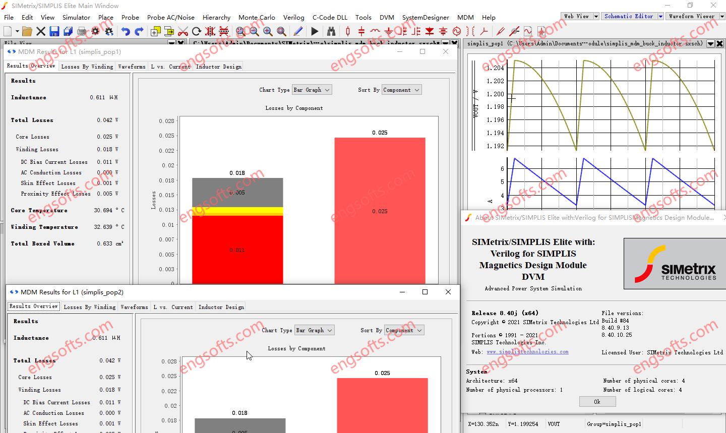
SIMetrix-SIMPLIS Elite with MDM 8.40 Tested Picture
Waveform Viewer Features
Independent X-Axis for Fixed Probes
It is now possible to force graph curves created by a fixed probe to have a separate X-axis, allowing independent zoom. Previously this could only be defined as a manual operation once the curve was plotted.
LTspice® Compatibility
The schematic editor can now open LTspice® schematics directly; just open the file in the normal way. If all models used are supported by the SIMetrix simulator, a simulation on the schematic can be run with only minimal changes required.
Design Verification Module Features
Testplan Editor
Testplans can now be created and edited using the built-in Testplan Editor. Along with removing the need for third-party spreadsheet or text editor software, the built-in Testplan Editor also provides assistance with various cell inputs. This includes drop-down selection lists and argument entry assistance.
In addition to cell entry assistance, the Testplan Editor also provides real-time error checking. Hover over colored cells to receive further information.
Testplan Wizards
Dynamically create a DVM tesplan to include only desired Objectives and inputs.
Three Wizards are available:
- DC-DC 1 Input 1 output
- DC-DC 1 Input 2 output
- AC-DC 1 Input 1 output
New Features for the SIMPLIS Simulator
Transformer Loss Breakdown per Winding
When simulating transformer losses with MDM, the Transformer Design tab in the MDM Results Window now provides a detailed textual loss breakdown of the winding losses for each winding. Users can now see how much winding loss of each type (DC bias, AC conduction, skin effect, and proximity effect) occurs per winding.
87 soft power magnetic materials have been added to MagDB. Their properties can be viewed in the MagDB window, and they can be selected for use in the Core tab of the main MDM window.
When adding a new core material to MDM’s database or modifying an existing material in it, users can now define a custom equation for calculating core losses. To do so, open MagDB, select a core material from the list, and click on the “Analytic Equations” button, which will bring up the Analytic Core Loss Equation Editor.
The equation is assumed to model core losses due to sinusoidal flux excitation, to output losses in W/m³, and takes as its input the frequency (in Hz), peak flux density (in T), temperature (in °C), and DC bias (in A/m). The user may write, using JavaScript, an arbitrary expression, utilizing some or all of the input parameters, that calculates volumetric core losses for the material. Some core material manufacturers provide such equations in their data sheets.
PFC POP Trigger Schematic Device
In order to start a SIMPLIS AC Analysis, a SIMPLIS POP Analysis must complete successfully first. For schematics of PFC circuits with AC input, up to now, a POP Analysis could only succeed under very specific conditions, i.e., when the switching frequency is an integer multiple of the AC line frequency – which is not the case in many PFC circuits.
The new PFC POP Trigger schematic device allows for a successful SIMPLIS POP and AC Analysis to be performed on schematics of analog-controlled PFC rectifier circuits including those with a variable switching frequency and those in which the switching frequency is not an integer multiple of the AC line frequency.
The PFC POP Trigger can be easily switched between AC and DC input, and in conjunction with the DVM Source or Power Supply Source can be used to quickly compare Bode Plots of the PFC with AC vs DC input.
New tests allow efficient use of the PFC POP Trigger with DVM.
New Features for the SIMetrix Simulator
Perfect Devices
Two new simulation models with perfect characteristics have been developed:
- Perfect diode with zero forward resistance and zero reverse current
- Perfect switch with zero ON resistance and infinite OFF resistance
The AC table feature that implements s and y parameters has been improved:
- s-parameter models may now have any number of ports. Previously only 1-port and 2-port devices were supported
- The schematic support has been improved with a symbol generation feature. A symbol with the required number of connections can automatically be generated given the Touchstone filename extension
Verilog-A code can now be debugged in real time using Microsoft® Visual Studio®. Visual Studio Community, Professional and Enterprise editions are supported for versions 2012 to 2022.
Instead of debugging the actual Verilog-A code itself, the ‘C’ code generated by the Verilog-A compiler is opened in the Visual Studio debugger. The debugger allows program flow to be followed as well as being able to view values of variables.